The Ondestrak
If you like the sound of the theramin, you may enjoy the Ondestrak. Based loosely off of the Ondes Martnot, the Ondestrak works by changing the pitch of a continuous note. [Devin_mccutchen] built his using an old gametrak controller. The controller looks pretty cool. We hadn’t seen that one before. Check out a more musical performance after the break.


Giant vacuum tube

When we saw this giant home vacuum tube, we thought it would go perfectly along side the giant LED lamp . Constructed from spare computer parts, a glass display dome and some EL wire, it is fairly convincing looking. If only he had shaped some characters with the EL wire, we could do a giant nixie tube project.


Illuminato

[Matt] sent us this very cool looking project called Illuminato. After brainstorming on how to improve upon the Arduino, and receiving lots of input on his ideas, [Matt] has put together this board that has several nice improvements. It has more I/O, more code space, faster serial communication speeds, built in PWM, and works with existing Arduino shields. Not only does it make these improvements, but it does it with style. The finish is quite nice, the layout is pleasing and it even has two rows of SMD LEDs on the back for some added geek cred. You can see a couple videos of it in action after the break.


Windows drivers for PS3 controllers

Recently, a Japanese coder on the DCEmu Forums released Windows drivers for DualShock 3 controllers. While the drivers only support using the controllers over USB and not bluetooth, they do include force feedback and Sixaxis support. Included with the drivers is a configuration tool, and though it appears to be in Japanese there is some explanation of how to use it included in the forum post. We have not tested these personally, but you can try out the drivers for yourself by downloading them from the forum here.
[photo: William Hook]


Putting FD lenses on a D60

[Peter] sent in this really slick project where he ads an FD lens mount to a cannon EOS D60. He already had a collection of nice lenses and didn’t want to waste them. After finding some a donor camera for the FD mount, he purchased a cheap D60 to graft it onto. While his first impulse was to simply glue the new mount onto the front of the camera, it was evident that this would hold the lenses too far from the sensor. The camera went under a bit for a while and luckily, no real damage was done to the mirror housing. The final result seems to work very well, there are example galleries available on his site.


N8VEM single board Z80 computer

The N8VEM is a homebrew computer project based on the classic Z80 microprocessor. It’s designed to be easy to build using large TTL DIP components instead of SMD devices. It runs the CP/M operating system and all drives are virtual in RAM/ROM. While the base hardware is interesting, we really like the potential for expansion using a backplane. Have a look at the project’s Hardware Overview to see extra boards like the bus monitor and the prototyping board. We found out about this project on [Oldbitcollector]’s blog; he’s using a Parallax Professional Development Board to create a VT100 terminal for the N8VEM.


Resistive ladder volume control

[jefffolly] published some straight forward plans for a passive volume control. It uses a resistive ladder built across the contacts of 12W rotary switches. Each resistor provides a 5dB difference, and he recommends using 0.1% tolerance resistors to maintain accuracy. The use of discrete resistors instead of volume pots means that the output is much more predictable. All of the RCA sockets were connected using oxygen-free copper wire.


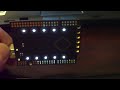
Wireless BlinkM control

[John] has been working with several BlinkM RGB devices. He’s created a controller to talk to each of the BlinkMs wirelessly and change their behavior. The core is an old relay tester box used to test telephone circuits. Each of its four knobs are connected to the analog inputs on the Arduino. The signal is transmitted using RFlink devices. Each BlinkM is paired with an ATmega168 and receiver. The control box also has a switch to send the same signal to all of the devices at the same time. The transmit and receive code are available on his site. You can find a video of it embedded below.


DC gearmotor teardown

The RepRap project has made heavy use of the Solarbotics GM3 Gearmotor as part of their extruders. Unfortunately they’ve proven to be underpowered for the task and the plastic gears could cause future problems. [Zach] decided to investigate some other options. He bought a pile of motors from Kysan to try out. He posted a teardown of one of the motors on Flickr. He found it not only easy to disassemble, but the metal gears were also easy to put back together. Next up is testing it on the machine.


Intel 4004 internals

The silicon wizards at Flylogic have certainly posted an interesting chip this time around. The Intel 4004 was the first widely used microprocessor. The logic gates are much larger than you’d find in modern chips. The unique feature is that each gate is designed to make the most efficient use of the silicon instead of the standardized shapes you find now. They’ve uploaded a full image of the chip.
For an introduction to silicon hacking, we reccomend [bunnie]’s talk from Toorcon and [Karsten]’s talk from 24C3. You can find many more posts on the topic in our silicon tag.


30's style regenerative receiver

[Des] sent in this really cool writeup on building a Regenerative receiver using VFDs. Regenerative receivers are basically short wave radio receivers that use positive feedback to more finely tune the signal. Though they can be built with modern components, [Des] wanted to try to make something that not only looked like it was made in the 30’s, but actually used the same technology. He utilized some VFDs in various places where vacuum tubes were needed. After building, [Des] found that the unit performed very well, better than his authentic 30’s radio that he compared it with. Those VFD’s seem to be everywhere recently. We did the story on using them as amplifiers, and and building display drivers for them too.


NoiseAXE minisynth

The NoiseAXE is a miniature synthesizer based on the Picaxe 08M microcontroller. Its operating principle is fairly simple: a conductive stylus touches the leg of one of eight resistors to play one of eight notes, while a photoresistor controls the amount of modulation, creating a variable vibrato effect. While the synthesizer’s output is rather limited (the NoiseAXE isn’t exactly a Yamaha DX7), it’s still a pretty cool little project; you could use its unique sounds to add that gritty analog touch to your next electro hit. Check out the video clip below to see and hear it in action.
[photo: rarebeasts]


Atari Xbox 360 controller

It’s amazing what [Ben Heckendorn] can manage to crank out in just five hours. This time it’s a wireless Xbox 360 controller stuffed inside an Atari 2600 controller. The guts are from a Guitar Hero 3 controller. It’s a fairly compact board and [Ben] used thin ATA wire for the connections. While it doesn’t have all the buttons of a true Xbox controller, this 3600 controller has enough to make it useful in arcade games. The joystick portion was reused without any modification. Things like the guide button and ring of light are located underneath.


Robot that shovels snow automatically

Those of you that live in snowier climates will drool over the I-Shovel, a battery powered robot that shovels the snow off your driveway, saving you countless hours of backbreaking labor over the course of a single winter. Its inventors claim that, despite its relatively underpowered motor, it keeps the driveway clear even in heavy snowfall; the trick, apparently, is that the robot constantly monitors the amount of snow on the driveway and springs into action whenever a significant but manageable layer has built up. Unfortunately, the I-Shovel is still a prototype, but with any luck you’ll be able to actually buy one soon. If you’re impatient, of course, you could always try building your own.
[via Toolmonger]


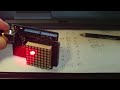
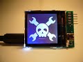
How-to: Digital picture frame, 100% DIY

There are a ton of digital picture frame tutorials out there. Most are old laptops with crafty case reconfigurations that fit a photo frame profile.
We set out to build a 100% DIY, scratch-built digital picture frame. Our frame has a 12bit color LCD, gigabytes of storage on common, FAT-formatted microSD cards, and you can build it at home. We’ve got the details below.
Concept overview

The bitmap images are stored on common, PC-readable microSD cards. A PIC microcontroller reads the images over a three wire SPI bus. The PIC processes the image data and writes it to a color LCD over a unidirectional, 9bit SPI-like bus. A configuration file on the SD card defines the delay between images.
Hardware

Click for a full size schematic image (PNG). The circuit and PCB are designed using the freeware version of Cadsoft Eagle. All the files for this project are included in the project archive linked at the end of the article.

Microcontroller
We used a Microchip PIC24FJ64GA002 28pin SOIC microcontroller (IC1) in this project. We really like this chip because the peripheral pin select feature lets us put important features on the pins we want; this gives a smaller, simpler, more compact PCB. Each power pin has a 0.1uF bypass capacitor to ground (C1,2). The internal 2.5volt regulator requires a 10uF tantalum capacitor (C12). The chip is programmed through a five pin header, SV1. R1 is a pull-up resistor for the MCLR function on pin 1. Read more about this chip in our PIC24F introduction.
A 32.768kHz crystal (Q1) and two 27pF capacitors (C10,11) provide an oscillator for the real-time clock calendar (RTCC). These parts are optional, the initial firmware doesn’t use them. The RTCC could be used as part of a function that superimposes the current time on the screen. Buttons connected to the programming header could be used to set the time.
SD card
MicroSD cards are completely compatible with regular SD cards, microSD cards can be used in an SD card reader/writer with an adapter. We tested several microSD card holders, and settled on one from SparkFun Electronics. The microSD card requires a bypass capacitor between the power pin and ground (C3). An LED indicates microSD read activity, but its also useful for general debugging (LED1, R2).
Color LCD 128×128 Nokia knock-off
This project is designed around SparkFun’s $20 color LCD panel. The LCD logic runs at 3.3volts and requires a decoupling capacitor (C4). The LED backlight requires a separate 7volt supply, and appears to have an internal current limiter because example designs don’t use external resistors.
The LCD has a separate input for the 3.3volt display supply. Many report noise in the display if this voltage isn’t clean. We used a ferrite bead (L1) and 0.1uF capacitor (C5) to filter the supply, and haven’t experienced any problems. This even worked on a dirty home-etched prototype. The ferrite bead type isn’t important, we used one left over from our tiny web server project.
The small connector is easy to solder on a professional board with a solder mask, but buy several as insurance. SparkFun has a PCB footprint for this part in their Eagle parts library, but the spacing between the pads is smaller than Olimex or BatchPCB will manufacture. We fudged it by decreasing the pad size to get more space between. Don’t depend on the connector to hold the LCD in place, use tape to hold it down. We used sticky-tack to attach the LCD temporarily.
We prototyped an LCD carrier board prior to sending the final design for manufacture. We recommend against using a ground fill under the connector without a solder mask.
Power supply
A 3.3volt supply, provided by an LD1117S33 (IC2), powers the PIC, microSD card, LCD logic, and LCD display. IC2 requires a 0.1uF bypass capacitor (C6) on the supply side, and a 10uF capacitor (C13) on the output. We used the same tantalum capacitor that we used for the PIC internal regulator.
The LCD backlight is powered by an LM317 adjustable regulator (IC3) configured to 7volts with 240 (R5) and 1100 (R6) ohm resistors. C7 and C8 are 0.1uF bypass capacitors for the LM317.
J1 is a SMD power jack for a common 2.1mm DC barrel plug. C11 is a 10uF electrolytic capacitor that smooths any lag in the supply voltage. C11 has a maximum 16volt input rating, so the supply voltage is best kept under 12volts. 9-12 volts is probably the idea power supply range.
PCB

Click for a full size placement diagram (PNG). L1, C5, and the LCD are on the opposite side. We can’t prototype two-sided boards in mom’s basement, so we sent this design to BatchPCB. Next week we’ll show you how we did it.
Partslist
| Part | Description |
| IC1 | PIC 24FJ64GA002 (SOIC) |
| IC2 | LD1117S33 3.3volt regulator (SOT223) |
| IC3 | LM317 adjustable regulator (SOT223) |
| U$1 | Color LCD 128×128 Nokia knock-off |
| - | Nokia knock-off connector |
| C1-8 | 0.1uF capacitor (0805) |
| C10,11 | 27pF capacitor (0805) |
| C12,13 | 10uF tantalum capacitor (SMCA) |
| C14 | 10uF electrolytic capacitor (SMD) |
| L1 | ferrite bead (0805) |
| LED1 | LED (0805) |
| Q1 | 32.768kHz crystal |
| R1 | 2000 ohm resistor (0805) |
| R2 | 390 ohm resistor (0805) |
| R5 | 240 ohm resistor (0805) |
| R6 | 1100 ohm resistor (0805) |
| SD1 | microSD card holder |
| J1 | 2.1mm power jack (SMD) |
| SV1 | 0.1" male pin header, right angle |
Firmware
The firmware is written in C using the free demonstration version of the PIC C30 compiler. Learn all about working with this PIC in our introduction to the PIC 24F series. The firmware is included in the project archive at the end of the article.
FAT12/16/32 disk library
Microchip’s FAT 12/16/32 library gives us easy access to files stored on SD cards. We gave a detailed description of this library in our web server on a business card project. If you’re having trouble reading a card with the library, check that it was formatted in a digital camera or using Panasonic’s SD card formatter.
Nokia 6100 LCD driver
SparkFun has a basic 8bit color driver (ZIP) for the Nokia 6100. We ported it to the PIC, and updated it for the 2byte-per-pixel 12bit color mode. With a small amount of added complexity, the pixel write rate could easily be increased by using a different 12bit mode that delivers two pixels using 3 bytes.
The LCD uses a 9bit protocol, one bit more than most SPI hardware will handle. The first bit tells the LCD whether the next 8bits are data or a command. On the PIC 24F it’s impossible to manually bang in the first bit, and then use the SPI peripheral to send the remaining 8bits. We lose direct control of the pins when hardware SPI is enabled. The data entry has to be completely bit-banged, which dramatically reduces the screen refresh rate.
Reading Bitmaps
There are a ton of bitmap formats. Windows compatibility keeps everyone using the ancient Windows v3 format. We created two C structs to read the V3 bitmap data.
| Offset | Bytes | Bitmap file header |
| 0 | 2 | Always 0×42 0×4D (hex for BM) |
| 2 | 4 | File size (bytes) |
| 6 | 2 | Reserved, ignored |
| 8 | 2 | Reserved, ignored |
| 10 | 4 | Location in file of the first bitmap data |
Bitmap files start with a 14byte file header. The first two bytes are the letters ‘BM’, indicating a bitmap. If the first two bytes are correct, the firmware loads the information header. The last four bytes indicate the beginning of bitmap data, but the current firmware just assumes it will begin at the end of the headers.
| Offset | Bytes | Bitmap information header |
| 14 | 4 | Length of bitmap information header (40bytes for Windows V3 bitmaps) |
| 18 | 4 | Width (pixels) |
| 22 | 4 | Height (pixels) |
| 26 | 2 | Color planes, always 1 |
| 28 | 2 | Color bits per pixel (1, 4, 8, 16, 24 and 32) |
| 30 | 4 | Compression method, we only read uncompressed (type 0) |
| 34 | 4 | Image data length |
| 38 | 4 | Horizontal resolution (pixels per meter) |
| 42 | 4 | Vertical resolution (pixel per meter) |
| 46 | 4 | Number of colors, ignored. |
| 50 | 4 | Number of important colors, ignored. |
A Windows V3 bitmap information header is 40bytes long. The firmware verifies that the header length (offset 14) is 40, indicating a V3 bitmap. If the width (132), height (132), color depth (24), and compression (0) all check out, the image data is processed and output to the screen.
| Offset | Bytes | 24bit image bitmap data |
| 54+(3n) | 1 | pixel n red value |
| 54+(3n+1) | 1 | pixel n green value |
| 54+(3n+2) | 1 | pixel n blue value |
Bitmap images have uncompressed, 1:1 representations of pixel data stored in three byte sequences. The data starts at the lower right-hand corner of the image; first the red value, then green and blue. Wikipedia has a complete bitmap walk through.
If the color depth of a bitmap image (24bits) is greater than the LCD can display (12bits), we need to discard the least significant bits of color data. To convert from 24bit color to 12bit color, we just chuck half the color data; an 8bit value of 11110011 is pushed four bits to the right, giving 1111.
Firmware walk-through
- Init PIC, SD, LCD.
- Read config.ini, create if it does not exist.
- Use first character of config.ini to set between image delay.
- Look for images, open next image.
- Read and check bitmap file header for proper format.
- Read and check bitmap information header for version, size, color.
- Read and display each pixel value. Adjust bit depth as needed.
- Delay, then repeat from 4.
Preparing images


To keep this demo simple, the photo frame only displays the most common bitmap format. Images must be sized to 132×132pixels, with 24bit color.
- Open a picture with an image editing program.
- Draw a square selection box over the part of the image you want to use, usually using shift and drag.
- Crop the image.
- Size the image to 132×132pixels.
- Save the image as a windows bitmap, 24bits of color depth.
Other image sizes and formats could be supported with a firmware upgrade (PNG, JPG), especially with a pin-compatible microcontroller upgrade to a giant dsPIC 33F.
Using it
Put images in the root directory of a FAT formatted SD card. Depending on the last device to format the card, it might need to be formatted with a digital camera or the Panasonic SD formatter.
Optional: make a config.ini file with a text editor. Enter a single digit, from 0-9, to set the between picture delay. Save the file. If you don’t create your own config.ini file, one will be created for you with a 1 second delay.
Put the card in the socket, and plug in the digital picture frame. Images will cycle on the screen with the defined delay.
Taking it further
We see a lot of potential in this simple digital picture frame. Many features can be added with a firmware upgrade, some are the basis for future hardware.
- Display other image formats, scale images
- Random fades and wipes
- Display time and date over image, set with buttons connected to programming pins
- Extend the configuration options in config.ini to include longer delays, fade or wipe type
- Use a sub directory for images because there are some file limitations to the root directory of a FAT formatted SD card.
- Add an ethernet connection for networked display updates.
Download: dpf.v1.zip


You received this email because you are subscribed to the real_time feed for http://hackaday.com/feed/. To change your subscription settings, please log into RSSFWD.