In flight insect photo rig
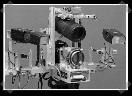
This amazing looking set up is for photographing insects in flight. While this is similar to a past project we covered, this one seems to have several improvements. There are no longer any arms that you have to position on either side of the insect. This system uses an additional lens, picture at the top, to detect the reflected laser light off of an insect. Requiring only 40 microseconds to determine if the insect is in focus, capturing a flying wasp shouldn’t be too hard. You can see four lasers in the pictures, two are IR and used for focus, the other two are simply to help the operator target their bugs.
[thanks Woeka]

25C3: Solar-powering your gear
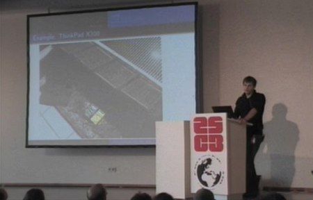
The 25th Chaos Communication Congress is underway in Berlin. One of the first talks we dropped in on was [script]’s Solar-powering your Geek Gear. While there are quite a few portable solar products on the market, we haven’t seen much in the way of real world experience until now.
[script] selected a four segment folding solar panel after some research. He pointed out that solar is currently more of a necessity technology than money saving since the panels can be very expensive. For connectors, he recommended ones that were safe, polarized, and difficult to short, like the RIA connect 230 series he used. Most of the device plugs were easily purchasable, but some had to be salvaged from old AC adapters. A key component of his setup was the adjustable voltage regulator. It’s based on the LTC3780 buck-boost controller which is 98% efficient and can be adjusted from 4V to 25V.
[script] covered some of the problems he ran into in use. The first was an Nokia that refused to charge until a resistor was added to reduce the current delivered. Less sensitive devices like portable peltier fridges will work without any issue. For laptop use, he ran into problems with demand spikes killing the power delivery. He added a large cap normally used in car audio systems to make power delivery more consistent. Laptops can consume as little as 15W during normal use, but when they’re charging the battery, the draw can jump to 50W. On his ThinkPad, he was able to turn off charging to prevent this. He monitored the performance of the panel by building a Kill A Watt style device using an ATmega8 to measure current and voltage and log it to EEPROM.
In conclusion, [script] stated that he was happy with his experience, but that it was still impractical to use the portable panel in anything other than direct sunlight.

Nintendo Sixtyfree Lite-R portable N64
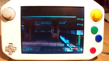
Nothing says Christmas like Nintendo 64 and benheck forum member [SifuF] has a treat for you. His Nintendo Sixtyfree Lite-R stuffs all the guts of at Nintendo 64 into a compact handheld package. It features dual joysticks and triggers. The display is a PSone screen with all of the extra board trimmed away. The part that really makes this project shine is the case. It’s vacuum-formed 2mm sheets of polystyrene. Another nice touch was the volume and screen brightness. They’re adjusted by holding down start and then using the other buttons. It doesn’t have internal batteries, but can run off of a 7.2V Infolithium.
[via Engadget]

Parts: 8bit IO Expander (PCF8574)
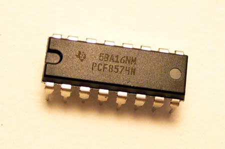
Sometimes a project has more sensors, buttons, or LEDs than your microcontroller has pins. The PCF8574 is an easy way to add 8 low-speed input or output pins to a microcontroller. A configurable address lets multiple PCF8574s exist on the same bus, so two microcontroller pins can control dozens of IO pins. We’ll show you how to use this chip below.
TI PCF8574 I2C 8bit IO expander (Mouser #595-PCF8574N, $1.86)
We found PCB footprints for this chip in i2c.lbr and micro-phillips.lbr on the Cadsoft Eagle library download page. The PCF8574 is controlled with the 2 wire I2C protocol, so we used our Bus Pirate universal serial interface to demonstrate this chip. The same basic operations will apply to any microcontroller.
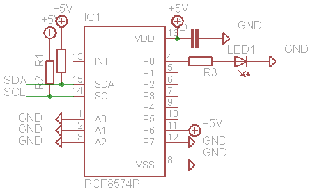
The schematic shows our simple test circuit for the PCF8574, here’s the datasheet (PDF). We powered the chip with 5volts, and used a 0.1uF decoupling capacitor (C1) between the power and ground pins. R1 and R2 hold the I2C clock and data bus at 5volts. We’ll use an LED to test the chip’s output features; P0 is connected to LED1 through current limiting resistor R3 (330+ ohms). P6 and P7 are tied to known states so we can easily test the chip’s input capabilities.
The PCF8574’s I2C address is 0100xxxy, with three bits (x) determined by the state of the address pins A2-0, and a final bit (y) that sets the read (1) or write (0) mode. Many PFC8574s can share an I2C bus by using different address pin settings. Since we tied the address pins to ground, the write address is 01000000 (0×40).
Output
The LED on P0 is controlled by writing a 1 (on) or 0 (off) to bit 0 of the byte following the write address.
I2C>{0×40 0b00000001} <–command
210 I2C START CONDITION
220 I2C WRITE: 0×40 GOT ACK: YES<–write address
220 I2C WRITE: 0×01 GOT ACK: YES<–output value
240 I2C STOP CONDITION
I2C>
{ issues an I2C start condition, followed by the write address, 0×40. The output value, 0b00000001, sets P0 high and the remaining bits low. } sends the I2C bus stop condition, ending the transaction. When the corresponding bit is set high, the LED turns on.
To turn the LED off, repeat the sequence with the corresponding output bit set to 0.
I2C>{0×40 0b00000000}<–command
210 I2C START CONDITION
220 I2C WRITE: 0×40 GOT ACK: YES<–write address
220 I2C WRITE: 0×00 GOT ACK: YES<–output value
240 I2C STOP CONDITION
I2C>
With P0 now set to ground, the LED turns off.
Input
Pins set to output high can also be used as inputs (datasheet page 1). In the example, P6 is held high (+5 volts) and P7 is held low (ground), but these could also be buttons, sensors, or other digital logic. The other pins are left floating and don’t represent valid data.
I2C>{0×40 0b11000000}<–command
210 I2C START CONDITION
220 I2C WRITE: 0×40 GOT ACK: YES<–write address
220 I2C WRITE: 0xC0 GOT ACK: YES<–output value
240 I2C STOP CONDITION
I2C>
First, we set the desired input pins to output high by writing 1 to the corresponding bits in the output value. Bits 6 and 7 set P6 and P7 to output high.
Now, we can read the pin. We did this operation with the Bus Pirate’s output set to binary mode so that the pin values are immediately obvious.
I2C>{0×41 r}<–command
210 I2C START CONDITION
220 I2C WRITE: 0b01000001 GOT ACK: YES<–address
230 I2C READ: 0b01000000<–pin state
240 I2C STOP CONDITION
I2C>
{ issues an I2C start condition, 0×41 is the read address, and r reads one byte from the device. } sends the I2C bus stop condition, ending the transaction.
The reply, 01000000, represents the state of the input pins. The most significant bit is 0 because P7 is tied to ground. The next bit is 1 because P6 is held high The other bits (0) are garbage data.
This is far from the only IO expander IC. Have you used another chip?
Don’t forget to catch up on any parts posts you may have missed.

You received this email because you are subscribed to the real_time feed for http://hackaday.com/feed/. To change your subscription settings, please log into RSSFWD.
No comments:
Post a Comment