Twittering washing machine
If you don’t have at least one twittering appliance in your household, you’re getting behind. The latest addition to the spread is a twittering washing machine. [Ryan] tells us that he kept accidentally forgetting to retrieve his clothing from the washing machine, resulting in smelly mildewy clothes. Now, his washing machine twitters to announce it is done. It also has a sign in the house that displays its status to help him remember. We’ve seen unborn babies and toasters twitter, what’s left? Remember those refrigerators that were supposed to let you know that you’re out of certain food? Why don’t we see a twittering fridge yet?

RFID dorm room door

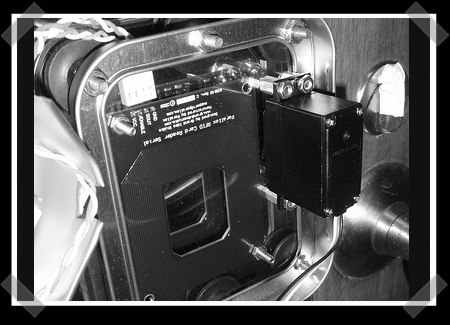
[Max] sent us his dorm room RFID controlled lock. While RFID door locks are nothing new, his implementation is very slick. The entire unit is attached with suction cups to a mirror on the inside of the door. It looks like it could be removed and put elsewhere in a matter of seconds. That’s pretty slick. Much cleaner than the touch sensitive dorm lock we saw last year.

Parts: I2C digital thermometer (TC74)

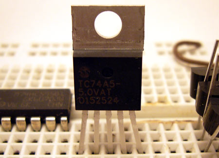
Microchip’s TC74 is an inexpensive digital temperature sensor with a simple I2C interface. It has a resolution of 1 degree Celsius, and a range of -40 to +125 degrees. This is an easy way to add temperature measurement to a project without an analog to digital converter. We’ll show you how to use the TC74 below.
Microchip TC74 digital temperature sensor (Octopart search, starting at $0.88)
The TC74 comes in five pin through-hole and surface mount packages, see the TC74 datasheet (PDF). We couldn’t find a Cadsoft Eagle footprint for any version of this part, if you know of one please link to it in the comments.

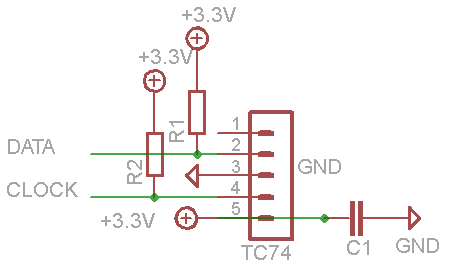
Different versions of the TC74 are calibrated for specific voltages, but all work from 2.7-5volts. The TC74A5 we used is most accurate when operating at 5volts, but we powered it from a 3.3volt supply. The I2C connection needs 2 pull-up resistors to hold the bus high (R1, R2), 2K-10K should work. C1 is a 0.1uF decoupling capacitor.
We used the Bus Pirate universal serial interface in I2C mode to test drive the TC74, but the same principals apply to any microcontroller. We powered the TC74 from the Bus Pirate’s 3.3volt supply, and used the on-board pull-up resistors to hold the I2C bus high.
| Command | Value |
| Select temperature register | 0×00 |
| Select configuration register | 0×01 |
The TC74’s write address is 0×9a, and the read address 0×9b. It has two, one-byte registers. Register address 0 holds the temperature reading, register 1 holds the configuration settings.
Configuration register
Bit 6 of the configuration register is 0 at power-on, and changes to 1 when the first valid temperature reading is available. Bit 7 is writable, and puts the TC74 in a power saving standby mode. Reading the register involves two steps: use a partial write command to select the register, then use the read command to retrieve the value.
I2C>{0×9a 1}
210 I2C START CONDITION
220 I2C WRITE: 0×9A GOT ACK: YES <–write address
220 I2C WRITE: 0×01 GOT ACK: YES <–select config register
240 I2C STOP CONDITION
First, we select the configuration register with a partial write command. This doesn’t actually write a value, it selects the register to read and write. { creates the I2C start condition, followed by the TC74 write address (0×9a) and the select configuration register command (0×01). } issues the I2C stop condition and ends the transaction.
Now we can read the contents of the register.
I2C>{0×9b r}
210 I2C START CONDITION
220 I2C WRITE: 0×9B GOT ACK: YES <–read address
230 I2C READ: 0×40 <– register value (01000000)
240 I2C STOP CONDITION
I2C>
The read address (0×9b) returns the one byte register value (r). The configuration register value, 0×40 or 01000000, shows that the device is out of standby (bit 7=0), and a valid temperature reading is available (bit 6=1).
The TC74 has a low-power standby mode. Enable it by writing 1 to bit 7 of the configuration register.
I2C>{0×9a 1 0b10000000}
210 I2C START CONDITION
220 I2C WRITE: 0×9A GOT ACK: YES <–write address
220 I2C WRITE: 0×01 GOT ACK: YES <–select config register
220 I2C WRITE: 0×80 GOT ACK: YES <–value to write (01000000)
240 I2C STOP CONDITION
I2C>
The register is written with single three-byte command. First we send the write address (0×9a), followed by the register to select (0×01), and finally the value to write (0×80). Only bit 7 of the configuration register is writable, the values of bits 6-0 are ignored.
Read the register again to verify that the command worked.
I2C>{0×9a 1}{0×9b r}
210 I2C START CONDITION <–first command sets register
220 I2C WRITE: 0×9A GOT ACK: YES <–write address
220 I2C WRITE: 0×01 GOT ACK: YES <–config register (1)
240 I2C STOP CONDITION <–end first command
210 I2C START CONDITION <–begin second command
220 I2C WRITE: 0×9B GOT ACK: YES <–read address
230 I2C READ: 0×80 <– register value (10000000)
240 I2C STOP CONDITION <–end second command
I2C>
The register value, 10000000, now shows that the device is in standby (bit 7=1). Notice that bit 6 is now 0, no temperature data is available.
Clear bit 7 to exit standby, then wait for bit 6 to return to 1 before reading the temperature register.
I2C>{0×9a 1 0b00000000}
210 I2C START CONDITION
220 I2C WRITE: 0×9A GOT ACK: YES <–write address
220 I2C WRITE: 0×01 GOT ACK: YES<–select config register
220 I2C WRITE: 0×00 GOT ACK: YES<–value to write (00000000)
240 I2C STOP CONDITION
I2C>
Temperature data is ready when the configuration register value returns to 0×40 (01000000).
Temperature
The temperature register is read in two steps. First, a partial write command selects the temperature register (0), then a read sequence returns the contents.
I2C>{0×9a 0}{0×9b r}
210 I2C START CONDITION
220 I2C WRITE: 0×9A GOT ACK: YES <–write address
220 I2C WRITE: 0×00 GOT ACK: YES <–select temperature register
240 I2C STOP CONDITION
210 I2C START CONDITION
220 I2C WRITE: 0×9B GOT ACK: YES <–read address
230 I2C READ: 0×18 <–grab one byte
240 I2C STOP CONDITION
I2C>
The temperature is an integer value of degrees Celsius, negative numbers are represented as a twos complement. Positive values from 0 to 127 degrees Celsius are simply represented by that value. Negative temperatures have bit 7 set, and range from -1 to -65 (255-128), see table 4.4 on page 8 of the datasheet. The hexadecimal value 0×18 is equal to 24 in decimal, so the temperature reading is 24C (75F).
Like this post? Check out the parts posts you may have missed.

You received this email because you are subscribed to the real_time feed for http://hackaday.com/feed/. To change your subscription settings, please log into RSSFWD.

No comments:
Post a Comment